Choosing the right flow check valve in 2026 is not simply a matter of matching pipe size. The valve must suit the fluid, operating pressure, expected flow rate, and installation conditions. A mismatch can cause unwanted backflow, excessive pressure loss, noise, or premature wear. Small details matter. Even the direction of installation can affect performance.
Start with the system, not the catalog. Confirm the fluid’s temperature, viscosity, and compatibility with valve materials. Then compare the required flow capacity and cracking pressure with the pump’s operating range. Consider whether the line experiences pulsation, water hammer, or frequent start-stop cycles. These conditions influence the choice between designs such as swing, lift, spring-loaded, and dual-plate check valves. Each has trade-offs; no single design is best for every application.
Selection also depends on maintenance access and reliable product documentation. Review pressure and temperature ratings, connection type, installation guidance, and test information from the manufacturer. Where downtime is costly, practical access for inspection may matter as much as the initial price. It is tempting to choose the smallest or cheapest option, but that decision can be difficult to defend later. And the data may not tell the whole story. This guide explains the key checks, common design differences, and questions to ask suppliers before choosing a flow check valve. Use the specifications as a starting point, then verify them against real operating conditions.

A flow check valve allows fluid to move in one direction and limits reverse flow. Forward pressure pushes its disc, ball, or plate open. When flow slows or reverses, the closing element returns to its seat. Some designs use gravity; others use a spring. Simple idea. But closure speed matters. A valve that shuts too slowly may allow backflow, while a fast-closing valve can contribute to pressure shock in the pipe.
The U.S. Department of Energy’s Improving Pumping System Performance guide reports that pumping systems account for nearly 20% of global electricity demand. That figure describes pumping systems, not check valves alone, but it shows why choosing compatible components matters. For a real installation, check the fluid, operating pressure, flow range, pipe orientation, and expected startup and shutdown conditions. A valve sized only by pipe diameter may chatter at low flow or restrict flow when demand rises. It’s an easy assumption to make—and worth questioning.
Tips: Confirm the manufacturer’s flow and pressure data against actual operating conditions. Note whether the line is vertical or horizontal, and ask about closure behavior and pressure surge risk. If the system carries dirty or viscous fluid, verify that the chosen design can handle it. A small detail, perhaps. But it can change the result.
Start with the fluid. Record its composition, viscosity, temperature, and any suspended particles. A valve handling clean water may behave differently with a thick process liquid. Note whether the fluid can corrode materials or leave deposits on the sealing surface.
Measure, don’t guess. Identify normal and peak flow rates, operating pressure, pressure surges, and acceptable pressure loss. Check the pipe’s diameter and installation orientation, too. Then clarify what the valve must prevent: reverse flow, drainage after shutdown, or contamination between process stages. These needs affect the required cracking pressure, sealing performance, and valve style.
Small details matter. For example, a pump that starts and stops often may create pressure changes that a steady-flow estimate misses.
Consider the operating environment and maintenance plan before selecting materials or connections. Will the valve face vibration, outdoor temperatures, limited access, or frequent cleaning? Confirm the expected service conditions against current technical documentation, and ask a qualified engineer to review unusual or critical applications. A tidy specification can still overlook a brief startup surge; I would treat uncertain measurements as assumptions, not facts. Record those gaps and verify them before ordering.
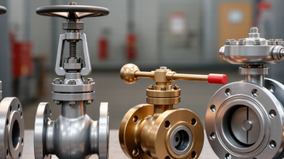
Choosing a flow check valve starts with understanding how the system moves fluid. A swing check valve suits steady, lower-velocity flow and needs room for its disc to open. A lift check valve can work well in compact, high-pressure lines, but usually creates more pressure loss. Dual-plate designs are lighter and shorter, useful where installation space is tight. Small details matter. Check flow direction, mounting position, expected flow rate, and the valve’s cracking pressure before comparing models.
Material choice affects service life as much as valve type. Stainless steel resists corrosion in many water and process applications, while ductile iron can be practical for larger, less corrosive lines. Bronze is often used in smaller water systems. Polymer bodies may suit certain chemicals, but temperature and pressure limits need close review. Seals matter too: an elastomer compatible with the fluid can still age quickly under heat or repeated cycling.
A common selection mistake is matching the valve to pipe size alone. A valve that is too large may not open reliably at low flow; one that is too small can restrict flow and raise wear. Consider fluid viscosity, suspended particles, pressure surges, and maintenance access. A clear water test may not predict performance with a thick or debris-bearing fluid. The final choice should follow the system’s actual operating data, not just a catalog description. I would still question any selection made without those details.
Choosing a flow check valve starts with the actual pressure conditions, not just the pipe rating. Record normal and peak inlet pressure, downstream pressure, and possible surge pressure. The pressure difference determines whether the valve opens reliably and how much loss it adds. Check the valve’s cracking pressure and rated working pressure against your operating range. ASME B16.34 provides pressure-temperature rating requirements for many valve types; confirm the specific material and temperature class before selection. Small details matter.
Match flow capacity to measured flow, not the largest available connection. A valve that is oversized may chatter at low flow; an undersized one can create unwanted pressure loss. Use the manufacturer’s flow coefficient data to estimate pressure drop at minimum, normal, and peak flow. The U.S. Department of Energy’s Improving Pumping System Performance sourcebook reports that pumping systems account for nearly 20% of global electricity demand. That figure is not a valve-sizing target, but it shows why avoidable system losses deserve attention.
Fluid compatibility needs equal care. Compare the fluid’s chemistry, temperature, viscosity, and suspended solids with the valve body, seat, and seal materials. For example, a seal suitable for clean water may swell or harden in a process fluid. Review documented material compatibility and inspect the actual fluid specification; generic labels can hide additives. I would still verify the choice under start-up conditions, where temperature and flow may differ from steady operation. A short field check can catch what a data sheet misses.
Match the valve’s pressure rating and flow capacity to the system’s operating conditions, then confirm that its wetted materials are compatible with the fluid.
Example screening scenario: a system operating at 10 bar and requiring 50 L/min is compared with three hypothetical valves, each rated to 16 bar and with illustrative flow capacities of 25, 45, and 75 L/min. Bars show the percentage of each rating used; values above 100% exceed the stated capacity. In this example, the 75 L/min candidate meets both numerical requirements. These figures are illustrative, not universal product specifications. Confirm pressure surges, actual pressure drop, sizing conditions, and fluid compatibility with the specific valve datasheet before selection.
Choosing a flow check valve starts with the actual operating conditions, not just pipe diameter. Match its flow range, pressure rating, temperature limit, and materials to the fluid and system. Check the cracking pressure against the pump’s available differential pressure; a valve that opens too late can restrict flow. Confirm the flow arrow and permitted mounting orientation, since some designs perform poorly when installed outside their specified position. Allow room to remove the cover or internals. Small details matter.
The U.S. Department of Energy’s Improving Pumping System Performance guide reports that pumping systems can account for 25–50% of electricity use in some industrial facilities. This is not a valve-specific figure, but it underlines why avoidable pressure loss deserves attention. Keep the valve accessible for inspection, and follow the maker’s guidance on upstream strainers and straight pipe runs. During maintenance, check for debris, corrosion, worn seating surfaces, and signs of reverse leakage. Record pressure drop and operating conditions so changes are easier to spot. A clean valve can still be the wrong choice if its spring or disc response does not suit the system. Recheck the selection after process changes; that step is easy to overlook.
Compare common check-valve designs against flow conditions, installation constraints, and maintenance needs. Confirm pressure, temperature, materials, orientation, and installation requirements against the selected valve’s technical documentation.
| Valve Type | Typical Applications | Installation Factors | Pressure Drop and Closure | Maintenance Considerations | Useful Selection Criteria |
|---|---|---|---|---|---|
| Swing check | Water, wastewater, and other services where flow can keep a hinged disc open. | Commonly installed in horizontal lines; some designs permit vertical installation with upward flow. Check the flow arrow and approved orientation. Allow space for the disc to move. | Often offers relatively low resistance when fully open. Slamming can occur if flow reverses rapidly or falls too low before closure. | Inspect the hinge, disc, seat, and deposits that could prevent full movement or sealing. | Consider when the line has steady flow and a simple, full-bore design is suitable. |
| Lift or piston check | Clean fluids in smaller lines and services where a guided closing element is appropriate. | Many models are designed for horizontal installation; some allow vertical installation with upward flow. Follow the model’s orientation instructions and provide access for servicing. | The guided disc or piston can create more flow resistance than a full-opening swing design. Closure behavior depends on design and operating conditions. | Check the guide, spring if fitted, seat, and moving element for wear, fouling, or sticking. | Consider when guided movement and a compact installation are priorities, and the available pressure differential can open the valve. |
| Dual-plate (wafer) check | Space-constrained water, HVAC, and process piping applications compatible with the valve’s materials and ratings. | Fits between flanges and generally has a short face-to-face length. Orientation varies by design; verify the manufacturer’s instructions, flow direction, and flange requirements. | Its short travel and compact design can support quick closure, but actual pressure loss depends on valve geometry, size, and flow rate. | Inspect plates, hinges, springs if present, and seating surfaces. Confirm that the valve can be removed safely for inspection. | Consider when installation length or weight is restricted and the piping layout suits a wafer-style body. |
| Axial-flow or nozzle check | Higher-flow systems, including pump discharge lines, where rapid, guided closure may be required. | Usually installed in line with the flow arrow. Straight-pipe requirements and permitted orientations are model-specific; check the technical documentation before locating the valve near bends or reducers. | Designed for streamlined flow and rapid response, but pressure loss and dynamic performance must be verified for the selected model and duty. | Inspect internal moving parts and spring components where applicable; plan access in accordance with the service manual. | Consider when flow stability, closure response, and system-specific hydraulic performance are central requirements. |
| Ball check | Some wastewater, slurry, or solids-bearing services, depending on ball, body, and seat design. | Permitted orientation varies. Check whether the chosen model is suitable for horizontal or vertical service and confirm the required direction of flow. | Pressure loss depends on the ball and passage geometry. The ball must move freely and seat correctly for reliable operation. | Inspect the ball and seat for wear, buildup, or damage; confirm that solids cannot obstruct movement. | Consider when the service fluid and suspended solids are compatible with the valve’s design and maintenance access is available. |
| All check-valve types | Any system requiring automatic prevention of reverse flow. | Size for the actual flow range, not pipe size alone. Observe the flow arrow, pressure and temperature ratings, approved orientation, flange or connection requirements, and any specified straight-run distances. Avoid locations with severe turbulence where practical. | Check minimum and normal flow, allowable pressure loss, reverse-pressure conditions, and the potential for water hammer. No single valve style eliminates water hammer in every system. | Establish inspection frequency based on fluid cleanliness, operating cycles, consequences of failure, and observed performance. Isolate and depressurize the line before opening equipment. | Verify fluid compatibility, required flow capacity, cracking pressure where applicable, leakage expectations, maintenance access, and applicable project or code requirements. |
Final check: A check valve’s orientation limits, pressure-drop data, pressure and temperature ratings, and maintenance procedure depend on the specific design. Use the manufacturer’s documentation and qualified engineering review for the actual system; do not assume that one installation rule or maintenance interval applies to every model.