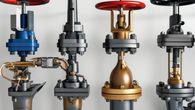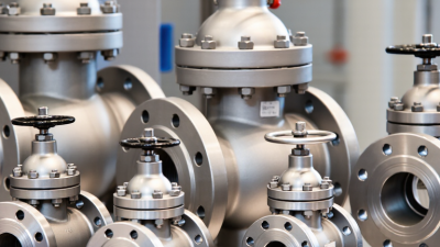
How to Choose the Right Automatic Recirculation Valve?

Selecting the right automatic recirculation valve begins with understanding the pump, not browsing a product catalogue. The valve must maintain safe minimum flow when the main discharge line throttles or closes. That duty sounds simple. It is not. Flow rate, pressure, temperature, fluid properties, and pump curve all influence the decision. A valve sized only by connection diameter may chatter, wear quickly, or fail to protect the pump.

Dr. Heinz P. Bloch, a respected turbomachinery reliability specialist, has emphasized, “Minimum flow is not a detail; it is a pump’s insurance.” This principle remains practical in modern process systems. Engineers should verify the pump’s minimum continuous stable flow, expected differential pressure, and transient operating conditions. They should also examine cavitation risk, noise, erosion, and backpressure. A valve that works beautifully at normal load may respond poorly during startup. That detail is often missed.

Field experience matters here. Picture a boiler-feed pump pushing hot water through a long discharge line. The bypass may open suddenly, producing vibration near an elbow. That sound deserves investigation. Manufacturer testing, certified materials, and documented sizing calculations improve confidence. Yet specifications are never a substitute for site data. I have seen selection decisions change after reviewing actual suction pressure and operating history. Sometimes the original design assumption was wrong. That is worth admitting.

This guide explains how to compare valve types, control characteristics, bypass arrangements, and maintenance requirements. It also highlights common selection mistakes. The best automatic recirculation valve is not simply the largest or most expensive option. It is the one that protects the pump reliably across real operating conditions.

How to Choose the Right Automatic Recirculation Valve?

Understanding the Purpose and Function of an Automatic Recirculation Valve

An automatic recirculation valve protects a centrifugal pump when process demand becomes too low. Reduced flow can cause overheating, vibration, cavitation, and unstable operation. The valve senses flow through the pump discharge line. When flow drops below the required minimum, it opens a bypass route. Fluid then returns to the suction vessel or another approved point.

Its function is more specific than simple pressure relief. A typical valve combines a check mechanism, a bypass passage, and controlled opening characteristics. At normal flow, the main valve remains open and bypass flow decreases. During a sudden demand change, the bypass opens without relying on an external signal. This response helps maintain the pump’s minimum continuous stable flow.

Selection should begin with the pump curve and the manufacturer’s minimum-flow requirement. Check the design pressure, temperature, fluid properties, differential pressure, and required bypass capacity. Line size alone is not enough. A small valve may create excessive velocity, while an oversized valve may respond poorly.

In pump-room inspections, blocked bypass lines and incorrect flow direction are common findings. They are simple errors with expensive consequences. I once assumed a higher pressure rating solved every problem. It did not; noise, flashing, and poor control still required attention. Confirm materials, installation orientation, and operating conditions with qualified engineers and verified calculations.

Identifying Key Process Conditions and System Requirements

Choosing an automatic recirculation valve starts with the pump’s real operating conditions, not only its nameplate data. Record flow range, discharge pressure, suction pressure, temperature, and fluid viscosity. Confirm the pump’s minimum continuous stable flow from reliable operating records or engineering data. A small mistake here can cause overheating, vibration, or unstable circulation.

Measure it directly. Determine the pressure differential available across the valve at minimum and maximum flow. Check whether the fluid contains solids, gas, or corrosive components. Vapor pressure also matters, especially with hot liquids, because excessive pressure drop may create cavitation. Review pipe size, downstream backpressure, and possible flow reversals before selecting the valve’s internal trim and materials. Do not guess.

System requirements extend beyond normal operation. Examine startup, shutdown, emergency trips, and rapid load changes. The valve must protect the pump during low-demand conditions without creating excessive noise or energy loss. Confirm the required fail position, response time, leakage limit, and temperature rating. A bypass that looks adequate on paper may perform poorly during cold starts or changing viscosity.

During commissioning, compare actual flow and pressure readings with the design assumptions. Field conditions often expose overlooked restrictions, inaccurate instruments, or an undersized return line. Keep a record of these findings, then ask a qualified engineer to review the final selection against applicable codes and maintenance access needs. Small details matter.

Comparing Valve Types, Materials, and Pressure Ratings

Choosing an automatic recirculation valve starts with the pump’s minimum continuous flow, not the pipe size alone. A valve that opens too late may allow overheating, vibration, or unstable operation. Mechanical automatic recirculation valves suit many centrifugal pump systems because they combine main-flow control, check action, and bypass protection. Modulating designs can provide smoother control where flow changes frequently. Keep it simple. Review the pump curve and actual operating range together.

Material selection depends on fluid chemistry, temperature, and erosion risk. Carbon steel can work well with clean, non-corrosive water under controlled conditions. Stainless steel offers stronger resistance to many wet and mildly corrosive services. More demanding fluids may require specialized alloys, but higher cost does not automatically mean better service. Check chloride levels, solids content, and velocity before deciding. A small compatibility mistake can shorten service life quickly.

Pressure ratings need careful verification. Compare the valve’s rated pressure and temperature with pump shutoff pressure, suction conditions, and possible pressure surges. The rating should cover the maximum credible operating condition, not only the normal reading on a gauge. Pay attention to pressure drop across the valve, especially at low flow. It can affect pump efficiency and bypass stability. Request material certificates, pressure-test records, and sizing calculations from qualified suppliers. The cleanest datasheet is not always the most reliable answer; field conditions often expose overlooked assumptions.

How to Choose the Right Automatic Recirculation Valve?

Comparing valve types, materials, and pressure ratings

Valve Type

Piston-style valves are commonly selected for high differential pressure and dependable minimum-flow protection. Diaphragm-operated designs are suitable when precise control and clean actuation are priorities.

Material Selection

Carbon steel is widely used for general hydrocarbon and utility service. Stainless steel is preferred for corrosive, wet, or chloride-containing fluids, subject to the applicable material specification.

Pressure Rating

The chart shows approximate ASME pressure-class ratings for carbon steel at 38°C. Final selection must consider temperature, fluid density, cavitation risk, flow rate, and the manufacturer’s certified rating.

Reference values shown in bar are rounded pressure-temperature ratings commonly associated with ASME Class 150–1500 carbon-steel valves at 38°C. Actual allowable pressure may vary by material group, design standard, and operating temperature.

Evaluating Flow Control, Reliability, and Maintenance Needs

Choosing an automatic recirculation valve starts with flow control, not valve size alone. The valve must protect the pump when process demand falls below its minimum continuous stable flow. API 610 identifies this operating limit as a critical pump design parameter. In practice, confirm the minimum flow, differential pressure, fluid temperature, and expected start-up conditions. A valve that opens too late can cause vibration, overheating, or unstable operation.

Reliability depends on how the valve behaves during frequent cycling. The U.S. Department of Energy reports that pumping systems can represent about 25% of industrial electricity use. Poor recirculation control may increase both energy loss and equipment stress. Look for stable trim movement, erosion-resistant materials, and a bypass path sized for real operating conditions. Small details matter. Particles, flashing, and repeated pressure shocks can shorten service life quickly.

Maintenance needs should be visible before installation. ISO 14224 promotes consistent equipment failure and maintenance data, which helps teams compare recurring problems. Select a valve with accessible inspection points and replaceable internal parts. Record opening pressure, cycle frequency, leakage, and vibration trends. Do not rely only on the vendor’s calculated service life. Field conditions often differ. That assumption can be wrong. A practical trial using operating data may reveal excessive cycling, unexpected noise, or inadequate minimum flow. Reliability is built through measurement, not confidence alone.

How to Choose the Right Automatic Recirculation Valve? – Evaluating Flow Control, Reliability, and Maintenance Needs

Evaluation Dimension Typical Design Requirement Recommended Valve Feature Why It Matters Selection Check
Pump minimum-flow protection Maintain the pump manufacturer's specified minimum continuous stable flow, commonly about 10–30% of rated flow depending on pump design and service. Automatic bypass opening below the minimum forward-flow set point. Reduces overheating, internal recirculation, vibration, cavitation risk, and damage to pump components. Confirm the required minimum flow from the pump curve and operating manual.
Forward-flow control Valve must remain stable across normal, turndown, and start-up flow conditions. Integrated check function with a characterized main-flow path and stable throttling behavior. Prevents unnecessary bypass flow and helps keep the pump operating near its intended duty point. Compare the valve flow coefficient, pressure-drop curve, and pump system curve.
Bypass capacity Bypass should pass the required minimum-flow rate at the available differential pressure. Bypass trim sized for the specified flow, pressure drop, flashing risk, and noise limit. An undersized bypass may not protect the pump; an oversized bypass can waste energy and cause unstable operation. Check bypass flow at minimum, normal, and maximum differential pressure.
Pressure and temperature rating Design pressure and temperature must cover normal operation, start-up, shutdown, and credible upset conditions. Pressure class, body material, seals, and trim rated for the complete service envelope. Improves pressure-boundary integrity and reduces the risk of leakage or premature material degradation. Use the applicable piping code, pressure-temperature tables, and design margin required by the project.
Cavitation and flashing control Avoid excessive local pressure reduction when liquid vapor pressure may be approached. Anti-cavitation or multi-stage pressure-reducing trim where high differential pressure exists. Limits noise, vibration, erosion, and loss of flow-control performance. Evaluate inlet pressure, outlet pressure, temperature, vapor pressure, and predicted velocity.
Fluid compatibility Wetted materials must tolerate the fluid's temperature, chemistry, solids content, and concentration. Corrosion-resistant body and trim; hardened surfaces or wear-resistant materials for abrasive service. Reduces corrosion, erosion, sticking, and leakage at seats and moving components. Review chemical compatibility, particle size, solids concentration, and corrosion allowance.
Response during start-up The bypass should open reliably before the pump reaches an unsafe low-flow condition. Low cracking pressure, correctly selected spring characteristics, and dependable check-disc movement. Protects the pump during filling, line pressurization, and low-demand operation. Verify opening and closing points against the actual pump start-up sequence.
Reliability and failure behavior Valve should provide predictable protection without external power where process safety requires passive operation. Self-actuated design with few moving parts and a defined fail-safe or fail-preferred position. Reduces dependence on instruments, cables, actuators, and control-system availability. Document the consequence of a stuck-open, stuck-closed, or leaking condition.
Maintenance access Inspection and service should be possible without removing extensive piping or nearby equipment. Replaceable trim, accessible internals, standard gaskets, and clear disassembly instructions. Shortens downtime and lowers lifecycle labor costs. Check access clearance, isolation points, lifting requirements, and spare-parts availability.
Inspection frequency Inspection interval should reflect service severity, duty cycle, fluid cleanliness, and operating history. Condition-based inspection supported by pressure, temperature, vibration, or bypass-flow monitoring. Early detection of sticking, erosion, seat leakage, and abnormal bypass flow helps prevent pump damage. Set inspection intervals using risk assessment and plant maintenance procedures rather than a universal schedule.
Installation orientation Installation must support correct check-disc movement, drainage, venting, and access. Clearly marked flow direction and an orientation permitted by the valve design. Incorrect orientation can cause premature wear, unstable operation, or failure to open. Confirm piping layout, support requirements, straight-run needs, and access for testing.
Noise and vibration Noise and mechanical vibration should remain within site and applicable regulatory limits. Low-noise trim, controlled velocity, adequate pipe supports, and avoidance of severe cavitation. Protects personnel, piping, instruments, and valve internals. Request predicted sound level and vibration assessment for high-pressure or high-velocity service.
Energy efficiency Minimize bypass flow and permanent pressure loss while preserving minimum-flow protection. Accurately sized valve and bypass trim matched to the pump's actual operating envelope. Lower unnecessary recirculation reduces pumping power and process heat generation. Estimate annual energy loss from bypass flow and pressure drop at expected operating hours.

Note: The flow percentages and selection practices shown are typical engineering references, not universal design limits. Final valve sizing and material selection should be verified against the pump curve, process data, applicable codes, and the valve manufacturer's certified performance information.

Selecting a Suitable Valve and Verifying Its Installation Fit

Choosing the right automatic recirculation valve starts with the pump, not the valve catalog. Confirm the pump’s minimum continuous flow, discharge pressure, fluid temperature, and expected operating range. The valve must pass enough flow to protect the pump during low-demand conditions. Its pressure rating should exceed the system’s maximum pressure, including possible surges. Material compatibility also matters, especially with hot, abrasive, or chemically active fluids.

Installation fit deserves equal attention. Measure the existing pipe size, flange standard, face-to-face length, and available clearance before ordering. Check the flow arrow carefully; reversing the valve can prevent proper recirculation. The return line should lead to a suitable suction point, tank, or process line without excessive backpressure. Leave room for inspection and removal. A datasheet may look complete, yet field dimensions can still disagree. That small mistake can delay commissioning.

Tips: Compare the valve’s minimum flow setting with the pump curve. Confirm the bypass line size and pressure losses. Inspect gaskets, bolts, supports, and alignment before tightening. During startup, observe vibration, noise, discharge pressure, and bypass flow. Do not rely only on a visual check. A valve can fit physically but perform poorly under real conditions. Recheck the installation after several operating cycles, because thermal movement and pipe stress may reveal problems later.