A 4 way valve is a directional control component that routes fluid or refrigerant between connected passages. You may find one in hydraulic equipment or in a heat pump, where it helps change the direction of refrigerant flow. In a heat pump, that change lets the system switch between heating and cooling modes. The valve does not create heat or pressure. It redirects flow within a larger system.
Inside, a movable slide or spool connects selected ports while closing others. An electrical coil, pilot pressure, or mechanical force may shift that internal part, depending on the valve design. The result is a different flow path. Small shifts matter. A sticking valve can affect comfort, pressure, or system performance, though similar symptoms may come from other faults. Diagnosis should consider the complete system, not the valve alone.
This guide explains the main parts of a 4 way valve, how its ports and internal passages work, and what happens when it changes position. It also describes common uses, basic operating principles, and signs that may suggest a problem. Port labels and switching methods vary by model, so a diagram or manufacturer’s specifications are useful references. Not every valve follows the same arrangement. Understanding that limitation helps prevent confusion when comparing equipment or discussing a repair with a qualified technician.
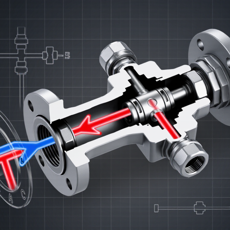
A four-way valve is a refrigerant-routing valve with four connections and two switching positions. The ports usually connect to the compressor discharge, compressor suction, indoor coil, and outdoor coil. In one position, hot discharge gas enters the outdoor coil; the indoor coil returns refrigerant to suction. Switch positions, and the indoor coil receives hot gas instead. That is the basic change between cooling and heating. Not magic.
A small solenoid pilot commonly shifts the valve’s internal slide, while pressure differences help move it. The compressor keeps running; the valve redirects its flow. In practice, port labels and piping diagrams matter, because a reversed connection can produce the wrong operating mode. The IEA’s 2022 report, The Future of Heat Pumps, estimates global heat-pump installations could grow from about 180 million in 2020 to 600 million by 2030 in its Net Zero Emissions scenario. That is a scenario, not a guaranteed forecast, but it shows why dependable changeover components matter. ASHRAE’s HVAC systems guidance also treats reversing-cycle operation as a core heat-pump arrangement. One limitation: a four-way valve routes refrigerant, but it cannot fix poor airflow, incorrect charge, or a faulty control signal. That distinction is easy to miss.
In a typical air-source heat pump, the four-way reversing valve sits in the refrigerant circuit near the compressor, usually inside the outdoor unit. It connects the compressor’s discharge and suction lines with pipes leading to the indoor and outdoor coils. Look for four connections. Two pipes run toward the compressor: a hot, high-pressure discharge line and a cooler suction return. The other two lead to the coils, often through bends and insulation that make the cabinet look crowded. Its exact position varies by design, so trace the pipes instead of relying on a fixed location.
The valve does not change the compressor’s rotation. A small pilot solenoid shifts an internal slide, directing refrigerant through the appropriate coil path. In cooling mode, the indoor coil absorbs heat; in heating mode, it releases heat indoors. That matters. A wiring diagram shows the electrical command, while a piping diagram helps confirm each connection. When identifying the valve, note its body, four connected lines, and nearby coil pipes. Refrigerant lines may remain hot or pressurized after shutdown. The diagram can seem clearer than the cabinet. Sometimes, it isn’t.
In heating mode, the four-way valve redirects hot refrigerant gas from the compressor toward the indoor coil. The compressor raises the refrigerant’s pressure and temperature. Inside the valve, a sliding component changes which pipes connect. It is a routing change, not a heat source.
The hot gas enters the indoor coil and releases heat into the room air. As it cools, the refrigerant typically condenses into a liquid. The indoor fan moves air across the coil; warm air then comes through the vents. Meanwhile, the outdoor coil absorbs heat from outside air as refrigerant evaporates there. Even on a chilly day, some heat can be transferred. The exact temperatures depend on the system and conditions.
The description sounds simple, but actual operation has details. A technician can check pipe temperatures and pressure readings to confirm the refrigerant is moving as expected. A sluggish valve may cause weak heating or unusual temperature differences between lines. Not every symptom points to the valve, though. Airflow problems or low refrigerant can create similar clues, so diagnosis should consider the whole system.
Heating mode: The four-way valve routes hot compressor discharge gas to the indoor coil. Refrigerant leaving the outdoor coil returns to the compressor through the suction line. The chart shows whether each path is connected in heating and cooling modes.
In cooling mode, trace the refrigerant from the compressor. Hot, high-pressure vapor enters the four-way valve through its discharge port. Inside, a sliding spool redirects it toward the outdoor coil. There, the refrigerant releases heat to the air and condenses. The valve also connects the indoor coil’s outlet to the compressor’s suction line. Refrigerant evaporates inside, absorbing heat from the room.
That is the cooling path: compressor, outdoor coil, metering device, indoor coil, and back to the compressor. The spool does not create cooling; it changes which coil receives discharge gas.
A small pilot passage shifts the spool when the control system energizes or de-energizes the valve. The exact control logic varies by equipment, so wiring assumptions deserve a check. A brief pause matters. Poor switching can leave the spool between positions, causing noisy flow or weak cooling.
The valve itself is not a diagnostic verdict; airflow, charge, and coil condition still affect performance. AHRI Standard 210/240 uses 95°F outdoor air and 80°F dry-bulb, 67°F wet-bulb indoor air for standard cooling ratings. Those conditions help compare equipment, but field temperatures rarely stay so tidy.
In service, technicians can feel the outdoor coil warm as heat leaves the system, while the indoor coil becomes cool and damp. The reversal is simple in principle, less perfect in practice.
A 4-way valve reverses refrigerant flow in a heat pump, allowing the indoor and outdoor coils to exchange heating and cooling roles. Its ports connect the compressor, coils, and suction line. Because pressure conditions change during startup, shutdown, and defrost, checking only a steady operating reading can miss important loads.
Compare measured pressures with the valve manufacturer’s stated limits, including maximum working pressure and allowable pressure difference across the valve. These are not always the same rating. Check the documentation for the exact valve model and refrigerant, and consider operating temperature and pressure surges.
Small details matter. Use suitable, calibrated gauges at the specified test points, and record readings during relevant operating modes. A pressure reading within the limit at one moment does not prove every condition is safe.
It is easy to treat this check as a box to tick; in practice, test conditions and rating definitions deserve a second look. If readings approach a limit, stop and have a qualified technician investigate rather than assuming the valve can tolerate more.