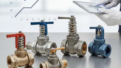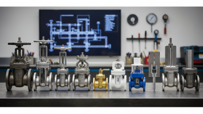
Choosing the right mechanical valve is a practical engineering decision, not a catalog exercise. A valve must match the fluid, pressure, temperature, flow rate, pipe material, and maintenance environment. One wrong specification can cause leakage, vibration, energy loss, or an expensive shutdown.
Industry reports show why this decision matters. Grand View Research estimates that the global industrial valves market will continue expanding through 2030, driven by water treatment, energy, chemical processing, and infrastructure upgrades. MarketsandMarkets also identifies automation, stricter emissions control, and aging facilities as major demand factors. However, market figures vary between reports. That difference deserves attention. Definitions are not always consistent.
Dr. David W. Spitzer, a recognized process measurement and control specialist, states, “A valve is a final control element, not merely a pipe accessory.” This principle should guide every selection. Start with service conditions, then compare ball, gate, globe, butterfly, and check designs. Review pressure ratings against ASME B16.34 requirements. Confirm leakage performance using ISO 5208 or the applicable API standard. Check actuator compatibility, seal materials, corrosion resistance, and replacement access. A stainless-steel body may look reassuring, yet it can still fail when the seat material suits the pressure but not the chemical exposure. Small details matter.
Field experience also changes the answer. A low-cost mechanical valve may appear efficient during installation. It may become costly after repeated cycling. The best choice is rarely the cheapest option. It is the one that remains safe, maintainable, and predictable under real operating conditions.
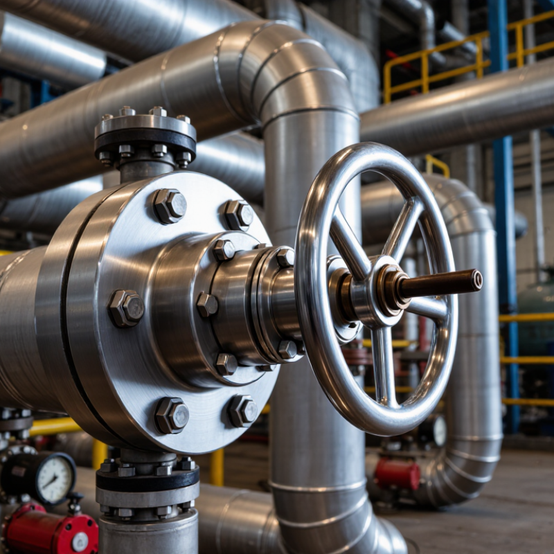
Choosing a mechanical valve starts with its operating principle, not its price. A gate valve lifts a wedge from the flow path, so it suits isolation but dislikes throttling. A globe valve uses a moving plug and seat, giving better flow control with higher pressure loss. A ball valve rotates a drilled sphere, offering fast, tight shutoff. Butterfly valves turn a disc around a stem and save space in large pipelines. Check valves open through forward pressure and close when flow reverses. Simple, but not foolproof.
Tip 1: Match the valve to the duty cycle. Frequent movement requires suitable stem, seat, and actuator materials. Tip 2: Check pressure, temperature, fluid chemistry, and flow coefficient together. The U.S. Department of Energy reports that compressed-air leaks can waste 20–30% of compressor output. Poor valve selection can add to that loss through leakage or unnecessary pressure drop. ISO 5208 leakage testing and ASME B16.34 design requirements provide useful verification points.
Tip 3: Define the failure position before ordering an actuated valve. Air loss may require fail-closed or fail-open behavior, depending on process hazards. Also inspect cavitation risk, water hammer, and maintenance access. A compact butterfly valve may fit beautifully, yet a damaged disc can interrupt the entire line. I would recheck the datasheet against real site conditions. Paper calculations sometimes miss vibration, dirty fluid, or operators needing a manual override. Safety margins should be practical, not decorative.
7 Tips for Choosing the Right Mechanical Valve
Defining flow, pressure, temperature, and media requirements prevents costly selection errors. Tip 1: Record normal, minimum, and maximum flow rates. A valve sized only for average flow may struggle during startup. Tip 2: Confirm pressure at the valve inlet and outlet, not only the pipe rating. The U.S. Department of Energy reports that pumping systems can represent about 20% of industrial electricity use, so unnecessary pressure loss deserves attention. Source: U.S. DOE, Improving Pumping System Performance, 2006.
Tip 3: Identify the fluid precisely. Water, steam, slurry, gas, and corrosive chemicals require different body and seal materials. Tip 4: Include viscosity, solids content, and chemical concentration. Small details matter. Tip 5: Check operating temperature and possible thermal shocks. ISO 5208:2015 defines standardized leakage tests for industrial valves, but field conditions can still expose weak seals or unsuitable materials. Testing alone is not enough. Tip 6: Compare the valve’s pressure-temperature rating with the real operating envelope. Do not rely on nominal pressure alone. Tip 7: Specify the required control or isolation duty, including cycle frequency and emergency conditions.
A useful practice is building a simple duty sheet with seven fields: flow, pressure, temperature, media, materials, actuation, and leakage class. The European Process Safety Centre has repeatedly emphasized that equipment specification and operating data support safer process decisions. Source: EPSC, Process Safety Fundamentals. In practice, measurements are sometimes incomplete. That is the uncomfortable part. Mark assumptions clearly, verify them onsite, and request supplier test evidence before approval.
| Tip | Key Requirement | What to Define | Typical Engineering Data | Selection Guidance | Verification Before Purchase |
|---|---|---|---|---|---|
| 1 | Define the Flow Rate | Normal, minimum, maximum, and start-up flow rates; required flow direction; allowable pressure loss. | Water systems may be specified in m³/h or L/min. Valve sizing commonly uses the flow coefficient Cv, which relates flow to pressure drop. | Size the valve for the actual operating range rather than selecting only by pipe diameter. Avoid excessive oversizing, which can reduce control accuracy and cause unstable operation. | Confirm the calculated pressure drop, design flow, shutoff condition, and the supplier's Cv or Kv data. |
| 2 | Establish Pressure Requirements | Operating pressure, design pressure, inlet and outlet pressure, differential pressure, and pressure surges. | Pressure may be expressed in bar, kPa, or psi. A valve body rating must cover the maximum allowable pressure at the operating temperature. | Check both the pressure rating of the body and the maximum differential pressure across the closure element. Consider water hammer, pump shutoff pressure, and relief-valve settings. | Compare the required pressure-temperature rating with the applicable standard and the complete valve datasheet. |
| 3 | Specify Temperature Limits | Minimum and maximum continuous temperature, short-term temperature excursions, heating and cooling cycles. | Temperature is normally stated in °C or °F. Elastomer seals often have narrower temperature limits than metallic valve bodies. | Select body, seat, packing, gasket, and actuator materials for the complete temperature range. Steam, hot oil, cryogenic fluids, and rapid cycling require special material review. | Verify the pressure-temperature rating, seal temperature range, thermal expansion effects, and actuator limits. |
| 4 | Characterize the Process Media | Liquid, gas, or vapor; chemical composition; concentration; viscosity; solids content; toxicity; flammability. | Corrosive media may require corrosion-resistant alloys or suitable lining. Abrasive slurries can accelerate wear on seats, discs, balls, and stems. | Match wetted materials and sealing compounds to the media. For clean gases and liquids, consider contamination control; for solids-bearing fluids, consider a wear-resistant design. | Check chemical compatibility tables, corrosion allowance, material certificates, and any cleaning or decontamination requirements. |
| 5 | Choose the Appropriate Valve Function | Isolation, throttling, non-return, pressure regulation, emergency shutdown, or flow diversion. | Ball, gate, and butterfly valves are commonly used for isolation. Globe and characterized rotary valves are commonly used for throttling. Check valves prevent reverse flow. | Use an isolation valve for open-or-closed service and a control valve designed for continuous modulation. Do not use a standard isolation valve as a control valve unless its design permits it. | Confirm the required leakage class, response characteristics, flow direction, fail position, and service duty. |
| 6 | Confirm Size, Connection, and Installation | Nominal pipe size, end connection, face-to-face dimension, available space, flow direction, and maintenance access. | Common connections include flanged, threaded, socket-weld, and butt-weld ends. Valve size should be selected from flow and pressure-drop calculations, not from pipe size alone. | Match the valve connection and pressure class to the piping system. Allow room for actuator removal, packing adjustment, inspection, and future maintenance. | Check dimensional standards, flange compatibility, bolt pattern, installation orientation, support requirements, and accessibility. |
| 7 | Review Actuation, Safety, and Compliance | Manual or automatic operation; operating frequency; available air, electric power, or hydraulic supply; safety position. | Pneumatic actuators are widely used where fast operation and fail-safe action are required. Electric actuators are useful where electrical power and accurate positioning are available. | Define fail-open, fail-closed, or fail-in-place behavior according to process safety requirements. Include position indication, limit switches, solenoids, filters, regulators, and emergency operation where needed. | Verify torque or thrust margins, cycle life, ingress protection, hazardous-area requirements, functional safety needs, and relevant standards. |
Choosing the right mechanical valve starts with matching materials to actual system conditions.
Record the fluid, temperature, pressure, flow speed, and cleaning chemicals. A valve that performs well with cold water may fail quickly in hot, abrasive, or chemically active service.
Check the body, trim, seat, and seal materials separately. Stainless steel may resist corrosion, while reinforced polymers can reduce weight and chemical attack.
However, compatibility is not judged by one material alone. Strong oxidizers, solvents, and concentrated acids can affect seals differently. Always review published compatibility data and confirm the operating range with a qualified engineer.
Think about pressure cycling, vibration, and trapped particles.
Repeated temperature changes can harden elastomers and create leaks around the stem. Fine grit may score a soft seat.
I once saw a valve selected for chemical resistance, but its seal failed under repeated heat cycles. The material choice looked correct on paper. The operating pattern was missed.
Avoid pairing dissimilar metals without checking galvanic corrosion risks. Consider cleanliness requirements in food, water, or laboratory systems.
Ask whether the valve can be inspected, repaired, and tested without contaminating the line. Request traceable material records when reliability matters.
Small details matter. Even a compatible material may underperform when installation torque, surface finish, or flushing practices are poorly controlled.
7 Tips for Choosing the Right Mechanical Valve
Compare actuation methods before selecting the valve body. Manual handles suit simple, visible operations and occasional adjustments. Pneumatic actuators respond quickly, especially where compressed air already exists. Electric actuators offer precise positioning but need protected wiring and dependable power. Hydraulic actuation provides strong torque, though its supporting equipment adds maintenance. Check required torque, cycling frequency, response time, and available utilities. Do not size the actuator by valve diameter alone. Review pressure, temperature, fluid type, and shutoff requirements together. I once underestimated starting torque on a sticky line, causing delayed operation. That mistake changed how I review real operating conditions.
Control features also deserve close inspection. Select position indicators that remain readable beside insulation or pipe supports. Add limit switches when remote confirmation matters. Consider feedback signals, manual override access, and emergency positioning needs. A fail-safe function may protect equipment during power or air loss. For throttling service, verify the valve can control steadily, not merely open and close. Installation details often decide long-term reliability. Leave room for actuator removal, cable bends, and tool access. Match connection materials with the process fluid and surrounding environment. Confirm flow direction and mounting orientation from the technical documentation. Support heavy assemblies independently when piping cannot carry the load. Clean the line before installation. Small debris can damage sealing surfaces quickly. Finally, test full travel, feedback signals, and leakage under realistic conditions. Recheck the plan after installation; field access is often worse than expected.
Comparing actuation methods, control features, and installation factors
The chart shows a typical engineering comparison of common valve actuation methods. Scores range from 1 (low suitability) to 5 (high suitability) and may vary with valve size, process conditions, safety requirements, and installation environment.
When selecting a valve, check media compatibility, pressure and temperature ratings, required operating speed, fail-safe behavior, control accuracy, available utilities, maintenance access, and hazardous-area requirements.
Choosing a mechanical valve requires more than checking size and pressure ratings. Start by matching the valve material with the fluid, temperature, and operating pressure. Review maintenance access before installation. A valve hidden behind piping can turn a simple repair into a costly shutdown.
Ask how often seals, seats, and actuators need inspection. Choose designs with replaceable parts and clear service instructions. Check safety features, including pressure limits, fail positions, locking options, and leakage control. Small details matter. A visible position indicator can prevent a serious operating mistake.
Estimate service life under real conditions, not ideal laboratory conditions. Frequent cycling, abrasive particles, vibration, and temperature changes can shorten it. Compare purchase price, installation labor, spare parts, energy use, and downtime. The cheapest valve may cost more after two unplanned replacements. Field records and maintenance logs provide stronger evidence than sales claims. I once underestimated access space, and the valve itself performed well, but servicing it was painfully slow. That mistake still deserves attention. Ask for test certificates, material data, and documented performance limits. Confirm that technicians can obtain training and replacement components. Total cost is never perfectly predictable. A practical estimate, updated with operating data, is more reliable than a confident guess.